To get the full plans and directions for building these Simple Home-Made Oven Makes Plastics to Easy Work CLICK HERE
CRAFTSMEN who have had experience with thermoplastics such as Lucite and Plexiglas have learned that these materials can be bent and molded into interesting shapes. When heated, these plastics become as pliable as leather. Heating has usually been done in a kitchen oven, as this was the only available source of indirect heat; but the handicap encountered in utilizing the oven has restricted the class of work that could be accomplished, inasmuch as the forming process had to be carried on in the kitchen, very near to the oven. The loss of heat in a thermoplastic is quite rapid in the first seconds and this drop may be sufficiently great to prevent successful molding if too much time elapses between oven and form.
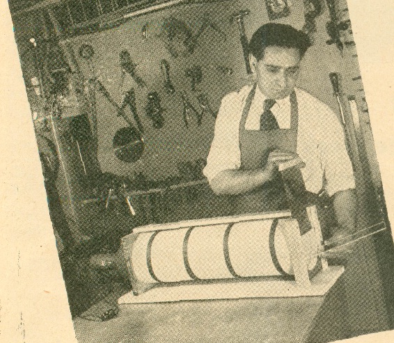
Now, with the development of this simple oven which makes use of an in frared ray lamp, it is possible to construct an oven for heating plastics right in the shop. Such an oven consists of a length of stovepipe set in a stand which holds the lamp at one end and provides a sliding cover, or door, at the other end. The oven shown in the photographs and drawing has been designed around an infrared lamp having a reflector of 7″ diameter. Construction of the unit should not be started until the lamp has been obtained. The groove cut in one of the end pieces to hold the reflector can then be made to fit the reflector. Materials required for construction of the oven are a 2-ft. length of stove pipe 7″ in diameter, a piece of asbestos 23″ x 24″, a wooden base measuring 3/4″ x 9″ x 29″, two end pieces 3/4″ x 8″ x 8 1/4″, two pieces 1/2″ x 1″ x 81/4″ for the cover guides, a top stretcher 1/2″ x 2″ x 25″, four wooden turnbuttons 3/8″ x 1/2″ x 1″, a piece of sheet metal 1/32″ x 6 1/2″ x 9″ for the cover, and a strip of wood 1/2″ x 3/4″ x 7 1/2″ for the knob or handle of the sliding metal cover.
Construction of the oven is started with the end pieces. Each of these pieces is to be set up in the lathe on a faceplate in order to turn the grooves that are to take the stovepipe and light reflector. The inside face of each piece must have a groove for the stovepipe. The outside face of one end piece must also have a recess for the reflector. Beyond the recess the center area is cut out entirely. The center of the groove* is located at a point 4″ from one end and 4″ from the edge. At these points, a small pilot hole is bored.The wood is mounted on a center screw faceplate and is set up in the lathe. A groove having an outside diameter of 7″ which is equivalent to the diameter of the reflector is cut in the face to a depth of 1/8″. The width of the groove should be at least 3/8″. The stock is then reversed on the faceplate so a groove of the same diameter can be cut in the inside face to a depth of 1/4″ to take the stovepipe as in Fig. 1. The center area, 6 1/2″ in diameter, is removed on a jig saw as in Fig. 2. The other end member will require a 7″ x 1/4″ groove cut in the inside face only, to take the stovepipe. A hole 6 1/2″ in diameter is cut also in the center of the second piece.
The finished end members are attached to the base with 1 1/2″ No. 8 flat head screws in holes bored and counter sunk in the base. After one of the end members has been fastened to the base, the stovepipe is placed in position and the second end member is attached to the base. The top stretcher is fastened to the end members with 1 1/4″ No. 7 flat head screws. The four turn buttons required to hold the reflector in place are shaped as shown in the sketch. A hole to take a 1″ No. 6 round head screw is bored in each button. The buttons are fastened to the end member so that they will engage the rim of the reflector and hold it in place as in Fig. 4. Each cover guide has a 1/16″ x 1/4″ rabbet cut along one edge to take the sheet metal cover. These guides are fastened to the end member with 1″ No. 6 flat head screws. The strip of wood that acts as the handle for the cover is attached to the metal with 1/2″ No. 3 round head screws set in holes drilled through the metal.
The asbestos covering is wrapped around the outside of the pipe where it is secured with friction tape as in Fig. 3. In use, the oven will have to be preheated a few minutes before the plastic is placed inside. For quickest results, small pieces of plastic should be placed near the end of the oven where the lamp is located.
To get the full plans and directions for building these Simple Home-Made Oven Makes Plastics to Easy Work CLICK HERE


